-GS-
Jay.M.Pasachoff@williams.edu wrote:
I have the pair of downloads. The results still don'tlook radial
enough to me to be real.
\
Jay
Hi Jay,
With respect to your comment on the "reality" of the orientation ofthe polarization
vectors in my broadband optical images, I really had no preconceivednotion as to
what they "should" be. However, I have now compared my resultswith the H-alpha
image of Ashok Ambastha which you kindly forwarded to me. UnlikeFe IV, I
would indeed expect a global map made in H-alpha to be similar to theboradband
continuum which contains it. Indeed, I find a remarkable agreementin the morphology
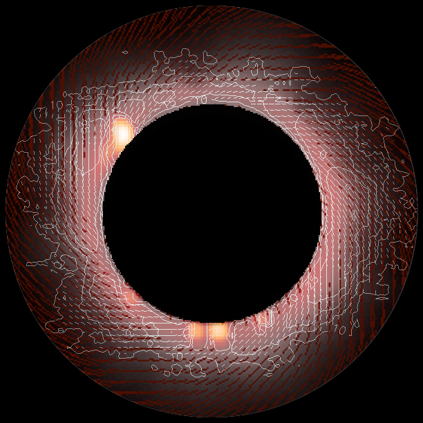
of my polarization map with Ashoks's. You can see this in theimage I have prepared
and is appended below. What I have done is overlaid Ashok's imageon mine, the same one which
I emailed you earlier and is on my server at
http://nicmosis.as.arizona.edu:8000/ECLIPSE_WEB/ECLIPSE_01/ECLIPSE_2001_REPORT.html
(for Ashok's benefit, to look at). Here, I resampled my imageto be at the same
spatial scale (a rough scaling based upon the lunar disk, but probablygood to about a percent
in scale) and reproduced it without my intensity contours overlaid*. I make Ashok's image
50% transparent so you can "see through" it, and thus see both hisset of polarization vectors (white)
and mine (red). It is of interest to note that he had sensitivityin the inner corona, and I in the
mid-corona. Recall, my polarimetric images were "deep" and theinner corona saturated.
The H-alpha image was apparently not as deep, so there was no sensibleflux recorded further
out, but is unsaturated with what looks like a good S/N right up tothe lunar limb.
In the overlaid image, as I re-stretched the components, the "gray"part of the corona
is from my broadband intensity image, and the "pink" is from Ashok's. The
pinkish-grey region contains flux from both images in combination.
Fortunately we DO have spatial regions of overlap, in a roughly annularzone centered at about 1.2 solar radii.
If you look at how his solution for the polarimetric field aligns withmine - taken with completely
different and independent instrumental systems - and calibrated andreduced separately, the
agreement is almost too good! Being a firm believer in Occum'srazor, I find it hard to believe
that we both have done it incorrectly in exactly the same way. The confirmatory nature of the
two results, I think, is pretty good evidence of the "reality" of bothpolarimetric solutions.
And, together we cover a much greater radial extent then separately.
* Note: I realized that the cosmetically inserted overlay of the innercorona and prominences
on the images on my web page (and sent to you earlier) are mis-orientedby 19.3 degrees.
This was the rotational offset angle between my "hi resolution" and"wide field/polarimetric"
cameras. When I clipped in the high-res image center, I forgotto re-orient it correctly. I
will, of course, fix that (probably over the week end) - but that isreally just a cosmetic
error in my composing the display image and in no way affects the quantitativeresults
of the polarimetric analysis.
If you like I can email you a .fits file with the actual theta anglesacross my field. In my
case the image is 253x253 pixels. You can see an image of thetheta solutions (polarimetric
direction at each pixel) on the above web page. But, it may be moreinstructive to have the
actual "numbers". Should I send that yo you as well?
Cheers,
-GS-