TSE 2003 & TOTAL ECLIPSE IMAGING
From the Flight Deck of QF2901/Antarctica 23 November2003 - A PRELIMINARY REPORT -
Glenn Schneider, Steward Observatory, University of Arizona
Collaborators: J. Pasachoff, J. Moskowitz, J. Friedland,J-L Dighaye, M. Gill & S. Kolodny
(This is just the beginning... come back again!)
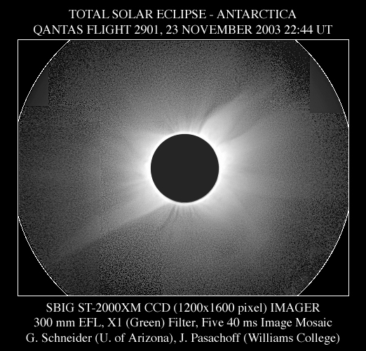
The glorious corona of the 23 November 2003 total solar eclipse capturedfrom the Boeing 747-400 ER flight deck of QANTAS (charter) Flight 2901over Antarctica at latitude 70°S. (Click the image for a slighly low-endclipped version to reduce the diffuse background).
For background information on the QF 2901 CLICKHERE
As many know, working with Captain John Dennis, pilot in command ofQF Flight 2901 (the Cryodon/QANTAS eclipse flight) I had the unique privilegeof defining the requirements, developing the lunar shadow airborne interceptscenario, and defining in detail the executable flight plan that lead toour immersion in the umbra for 2m 30s centered on 22:44 UT. Preliminaryinformation about the flight, in general form, was made available pre-flighthere. Now that the flight is history, the previously embargoed Mission& Planning Definition Overview which was presented to QANTAS airlines,is now publicly available and those who were on the flight may find thereport itself and attached appendices A and B of interest. Additionalpost-flight information will be posted on this web site in the weeks andmonths ahead.
An additional benefit of occupying the seatimmediately behind Captain Dennis on the flight deck, was the unfettereduse of the high quality 16inch x 28 inch window and open floor space between those two seatsto observe, photograph, and digitally image the eclipse. To make the bestuse of this opportunity, a collaborative imaging program was devised, anda four camera "common mount" three-axisgyro stabilized platform was constructed and used during the flight. The camera complement and imaging program was as follows:
1) SBIG ST-2000XMCCD Camera, graciously on loan from the SantaBarbara Instrument Corporation. The imaging program for the CCD camerawas devised by J. Pasachoff and S. Sousa (Williams College) and was autonomouslyexecuted under computer control during the flight. This program acquiredgreen-filtered coronal images, executing a repetitive sequence of 10, 20,and 40 millisecond exposures with an inter-exposure cadence of 4 secondsthroughout the total phase of the eclipse.
2) NIKON F5 35mm film camera, 400mm f/5.6 Vibration Reduction Lens,Fuji NPZ 800 film (push processed 2 stops to ISO 3200). This camera wouldprovide color imagery of the mid to outer corona to about 5 solar radii. A uniformly spaced series of exposures, with a cadence of 5.36 seconds,was executed between contacts 2 and 3. A log-normal series of exposuredurations 40 milliseconds after contact 2, ramping up to 160 millisecondsat mid eclipse, then ramping back down to 40 milliseconds prior to contact3 were taken.
3) PENTAX 35mm film camera, 500mm f/8 Tamaron Lens with 1.4x focal extender,Kodachrome K-64P film. This camera would provide color imagery ofthe inner to mid corona from just above the occulted photosphere to about1.5 solar radii. The exposure sequence with this camera was executedsynchronously with Camera 2, but the log-normal exposure durations beganand ended with exposure times of 10 milliseconds.
Both 35mm film camera were autonomously controlled with Umbraphileona Macintosh Powerbook.
4) SONY DCR TRV 900 NTSC, three CCD Digital Video Camera. Thiscamera, primarily, was intended as a platform guide camera streaming real-timevideo to the Macintosh screen display, but also was set to record the videoimagery during the eclipse.
The optical axes of the four cameras were co-aligned and mounted ona common platform. The common camera platform was inertially stabilizedby two orthoganally mounted KenyonKS-8 dual-gyro stabilizers. The platform, balanced to point upwardat 14.9 degrees (the altitude of the Sun at totality) was critically adjustedto null out any torques, and suspended by a bungie cord to allow free reactionagainst any change in aircraft attitude, orientation and also body jitter. The bungie cord was secured to the wall of the flight deck above the windowby means of a 70 lb. static load 6-inch diameter vacuum suction cup. The whole rig hung immediately behind the pilot's seat. Batteries,inverters, power supplies, computers, cabling, and other support equipmentwere velcroed to the back of the pilot's seat, to the flight deck floor,and anywhere else where room could be found.
AND... How Did We Get All This Stuff On The Airplane???SeeHERE.
In situ photographs of the equipment as integrated on the flight deckwill be added later.
PRELIMINARY IMAGING RESULTS
Below are some of the very first preliminary resultsfrom the imaging program. Check back again, as this will be updatedand expanded over time.
Digital image processing and composition by G. Schneider
SBIG ST-2000XM 1600x1200 CCD CAMERA (Green Filter)

CAVEAT EMPTOR: UNCALIBRATED
Five 0.04s EXPOSURE REGISTERED MOSAIC
30% Radial Median Intensity Profile Subtracted
Log10 Display, [3.9] dex (7950:1 Linear) Dynamic Range
(The artifacts will go away after calibration)
UPDATE 9 DEC 2003 - CALIBRATED IMAGES (fromwhich the mosaiced composite on the top of this page was made) NOW AVAILABLE:CLICKHERE for more on that.
Notes on above Image:
1) The above image is a mosaic made from five (5) of the 40ms exposurestaken as part of the CCD imaging program,
2) The camera platform pointing changed between images, thus providinga wider effective field-of-view. The original raw images are shownin thumbnail form below:

The image shown above was made from frames 11 - 17 of the 40ms imagingsequence. Frames 13 and 14 are excluded as the Sun was not in thefield of view of the CCD camera when those frames were taken. Sequentialframes are four seconds apart, hence frame 17 was taken 24 seconds afterframe 11.
3) The projection of the rotationally and translationally co-registeredfields onto the sky is illustrated in two figures below. The imagesare critically sub-pixel co-aligned on the features in the corona, noton the lunar disk. The apparent position of the moon moved significantlyw.r.t. the Sun between exposures.
The figure on the left is a simple co-addition of the offset pointedraw images after co-registration. As is apparent there is some amountof field overlap in portions of the wider mosaiced field. The figureon the right illustrates the number of frames which contribute to a laterdone median collapse of the five images. Black = 0, Dark Gray = 1, Middle Gray = 2, Light Gray = 3.
4) Prior to combining the registered frames a calibration dark/biasframe was subtracted from each. This calibration reference file wasmade from a median combination of 25 dark/bias frames taken on the aircraftimmediately prior to the start of the eclipse imaging sequence.
5) NOTE: At this point the individual frames have *NOT* been flat-fielded,so the intra-frame photometric calibration is not correct, and they cannotacdtually be properly combined without introducing artifacts in the combination. A flat-field reference file will very soon be provided by Steve Sousa anda proper image combination, devoid of the artifacts apparent in the topmostimage can then be done.
6) Ahead of obtaining and applying a reference flat, the registeredimages were nonetheless median collapsed (though that will have to be doneover again after flat fielding). Because the CCD has a very largenon-saturating dynamic range the information recorded cannot be shown ina single linear image. Below, the inner regions of the corona capturedin this image are shown:
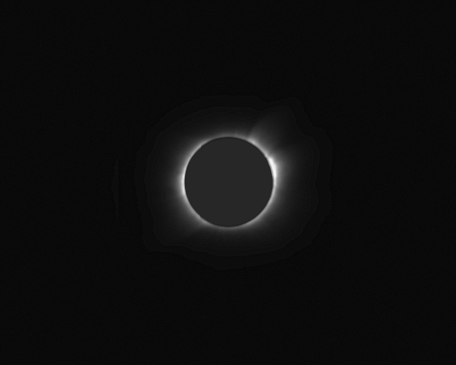
CLICK ME!
To step through a linear display series, increasing the display gainby factors of 2 in each step, click on the above image. (This is a QuickTimemovie; if your browser does not display it in-line then download and usea stand-alone QuickTime viewer).
7) More of the corona can be seen in a single image in a square rootdisplay. Below are two flavors: Above inner and mid corona, and belowmid and outer corona.
Again, the "seaming" artifacts will go away after flat-fielding.
7) More of the corona l structure can be seen in a single image in collapsingthe dynamic display range by taking the Logarithm (base 10 in this case)of the image. Note, for example, the coronal streamer at the lower rightwhich can be traced from the occulted solar limb (0.5 Rsun) out to 5 solarradii.

8) For better show the azimutally differentiated coronal features (streamersand holes) the underlying radial brightness gradient is partially subtracted. This was done by measuring the radial brightness profile, on the azimuthalmedian, in all zonal regions one pixel wide, then subtracting 30% of theintensity of that radial profile at every corresponding radial zone. 30% is subjective, but the criteria is to not oversubtract any local featureto a negative value, which could then not be represented in a log display. This "final" result is what was shown at the top of this page, and repeatedhere for contextual continuity:
The vertical striated "features" introduced in the corona on eitherside of the vertical axis of symmetry is due to display aliasing of thequantized subtracted radial profile. This can be easily eliminatedby simple 2 (or 3) point boxcar smoothing of the radial profile. I certainly will do this after repeating this process with the data afterit is flat-fielded.
Lastly, for now, on the CCD images, the same can be done for the 10msand 20ms CCD images. And then, when all are photometrically calibrated,all cam be combined onto a single final image to improve both the radialdisplay range and the signal to noise.
As a FINAL note here, the actual data images are larger in linear scaleby 4x, i.e., have 16x more pixels than shown above. A smaller formatwas used just for web viewing.
NIKON F5 with 400mm f/5.6 VR LENS and FUJI NPZ-800 Pushedto ISO 3200

CAVEAT EMPTOR: NOT COLOR CALIBRATED
Three EXPOSURE MEDIAN COMBINATION, 0.5s Total Exposure Time
50% Radial Median Intensity Profile Subtracted
Linear Display
Well, the hour got very late, so I won't describe this now in detailas I did the CCD images, but thought some would like a quick-look at thefirst results from the wider (400mm EFL on 35mm film) format film camera. Don't worry about the color balance, that will get fixed in final processing. The above image also has a radial median intensity profile subtracted (separatelyfor a 3 color plane R, G, B separation, then recombined after subtraction)but shown in a linear display. I also show this with only a 25% radialintensity filter (below, top), and also ORIGINAL image, without any suchradial intensity filtering (below, bottom):
Here is a thumbnail gallery of the full set of "useful" coronal imagesobtained with this camera. Some, unfortunately, not so well pointed,as you will see. None-the-less, the intention is to combine all thisinformation into a final high S/N color image in a process similar to thatdescribed for the offset dithered CCD images. To see this twice as largeclick on the gallery of images.

PENTAX with 500mm f/8 Lens, x1.4 Focal Extender, Kodachrome-64PFilm
| THIS FILM HAS BEEN SENT OUT FOR DEVELOPMENT AND TRANSFER TO KODAK PROPHOTO CD. RESULTS WILL BE POSTED AFTER THE DIGITIZED IMAGES ARE RETURNED. |
SONY DCR TRV 900 NTSC, three CCD Digital Video Camera.
| THIS DIGITAL VIDEO IS CURRENTLY IN THE POSSESSION OF J. MOSKOWITZ. A COPY IS EXPECTED SOON. SHOULD ANY SEGMENTS CONTAIN USEFUL OR INTERESTINGIMAGERY THAT WILL BE POSTED HERE. |
The image below was derived from raw hand-held digital video footagetaken by J. Friedland through one of the windows in the passenger cabin. This video was used in developing and testing "Good Frame Extraction" and combination algorithms which will be applied suitable footage recordedon the platform guiding camera. A full description of the video extractionand re-combination combination process is provided, and may be viewed byclicking on the image below.

CLICK ME!
Median Combination of 36 Video Frames Extracted from 15s of Footage
Critically Aligned Rotationally and Translationally
Two of the four cameras for which the results on this page are discussedare shown in the image below (the other two are on other side of the platform). Anybody venture a good caption for this photo?

More will be coming!!!!
http://nicmosis.as.arizona.edu:8000


